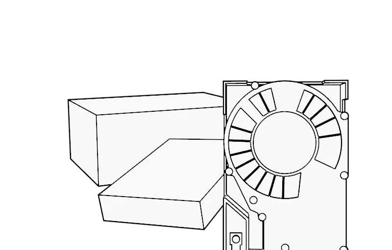
Micropolis 4221WD
Hard Disk Drive
Overview
| Model | Capacity | Size | Height | Interface | Bus Type |
|---|---|---|---|---|---|
| Micropolis 4221WD | 2050MB | 3.5" | SL | D/W | SCSI2 |
Specifications
| Size | 3 1/2" |
| Interface | SCSI-2 |
| Encoding Method | |
| Formatted Capacity | 2,050 MB |
| Disks | 5 |
| Heads | 9 |
| Cylinders | 4150 |
| Sectors | Variable |
| Buffer Size | N/A |
| Average Seek | 8.9. msec |
| Single Track | |
| Rotation Speed/Avg. Latency | 7200 rpm +/- 0.5% |
| Transfer Rate to / from. media | 20 Mbytes/sec Synchronous |
| Transfer Rate to / from buffer | |
| Tracks Per Inch (TPI) | |
| Bits Per Inch (BPI) | |
| Dimensions | 5.75"D x 4.0"W x 1.0"H |
| Weight | 0.00 lbs. |
Power Requirements
| +12V +/-5% | +5V +/-5% | Power | |
| Spin up | .5A | ||
| Read / Write | 1.52A | 1.2A | |
| Typical seeking | 13.5 Watts |
Notes
| Notes: | |||||||||||||||||||||||||||||||||||||||||||||||||||||||||||||||||||||||||||||||||||||||||||||||||||||||||||
Configuration and Jumper Options
SCSI ID Selection Up to sixteen devices (the host and fifteen targets) can be attached to the SCSI bus. These are selected with jumpers on the Option Jumper Block or on Auxiliary Connector J1B (use either but not both); see the Note below the J1B drawing for J1B usage. In multiple-device systems, each device must have its own Unique SCSI ID. The SCSI ID (drive address) jumpers are identified as ID0, ID1, ID2, and ID3. ID selection is binary, as shown below.
A jumper at PTY (Pins 17 and 18) selects the bus parity check option. The drive always generates parity regardless of this option.
Spindle Sync Signals Use of the MSYNC and SSYNC signals is optional. These signals are used as spindle synchronization reference. Auxiliary Connector J1B
Note: J1B is sampled at initialization for jumpers on pins 7-8, 5-6, 3-4, and 1-2 for SCSI ID3, ID2, ID1, and ID0 respectively; these connections (if not jumpered) are then released for the following usages: A dash character (-) at the end of a signal name indicates that it is asserted at the low level (i.e., active low) and negated at the high level. Drive Fault (XTFALT-) Output signal negated (Default); indicates no drive fault. Output signal asserted; indicates a drive fault condition. Slave Sync (SSYNC-) Use is optional; used as spindle synchronization reference. Remote LED- Open collector output; used to drive a user-supplied LED to indicate the drive is active. Ground (GND) Logic ground; provides signal ground. +5 Volts (+5V) 5 VDC (1A max); used to drive external LEDs. Write Protect (FAULT-) Input signal negated (Default); drive is not write protected. Input signal asserted; drive is write protected. |

